|
|
|
|
|
Engineering Data - Beams and Columns
|
|
| Notes to Table Note 1: Loads are governed by shear or web crippling. Note 2: For uniform beam working loads asymmetric sections are required to be adequately braced to prevent rotation and twist. |
Beam Loads The loads and deflections shown are based on simply supported beams uniformly loaded. For other loading configurations refer to Reference Tables (Table 1) in this Tab Section. |
|
Structural Data
|
|
| 1. Section Properties Section properties have been derived from 'as formed' shapes and are based on nominal dimensions and nominal base steel thickness. Nominal masses are calculated from the tabulated areas based on a steel density of 7850 kg per cu.m. For dead load calculations the tabulated masses should be increased by 10% to allow for rolling tolerances, and the result multiplied by 0.0098 to give corresponding dead load (self weight) in kN per m. run of section. Also note the beam and column loads do not make allowance for self weight of the section. When designing a structure in which the section forms an integral part, the self weight should be determined using the method described above and subtracted from the tabulated load. 2. Beam and Column Load Tables Ultimate load values have been calculated from the section properties as permitted by AS/NZS 4600 Cold Formed Steel Structures code. The guaranteed minimum yield stress Fy has been taken as 210MPa for plain channels, and the increase allowed resulting from cold forming has been determined in accordance with the code. The listed working loads have been derived from the ultimate load divided by 1.5. 2.1 Span or Column Length Listed value is to be taken as the distance between centres of supports. 2.2 Beam Load at Maximum Permissible Stresses In order to establish the table of working loads that can be carried by the corresponding section, the ultimate limit state loads that could be permitted by the code were first determined. These were divided by 1.5 to provide 'conservative' working loads. The load is considered to be uniformly distributed along the span and orientated with respect to the section, as defined by the diagrams to cause bending about X-X axis only. The webs of the beams are assumed to be unstiffened and have been checked for end bearing in accordance with clause 3.3.6 of AS/NZS4600:1996. Where this is critical the working loads have been appropriately reduced. This assessment has been based on a rigid support with the beam bearing on each support for a length equal to at least the straight length of web-depth of the basic section. |
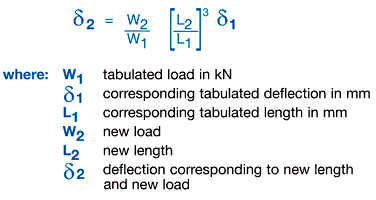
2.3 Deflection Deflections are calculated for the corresponding beam working load, using standard formulae. Deflections or uniformly distributed loads for conditions other than those tabulated may be calculated from the following:-  It is recommended that beam deflections generally be limited to the smaller of span/180 or 10mm and loads restricted accordingly. These limitations are based on ‘visual straightness’ with the latter value subject to variation to suit particular visual or other physical requirements. 2.4 Maximum Column Load Listed values of column load capacity are derived on the basis of a concentric axial load applied to the section, acting as a column with an effective length corresponding to the listed value, i.e. translational and torsional restraint available at the centres of supports. For other conditions of loading and/or restraint, reference should be made to the appropriate sections of AS/NZS 4600 Cold Formed Steel Structures. 3. Recommended Bearing & Connection Loads Listed values are based on extensive testing of components by Unistrut Australia Pty Limited using a factor of safety of 2.5 against failure of the connection. 4. Point Loads For point loads at midspan, the allowable loads are half the values shown in the tables. The deflection for the point load is obtained from: |