Unistrut Sections as Beams
The load capacity of Unistrut members acting as a horizontal beam, between two vertical Unistrut members acting as columns, is governed by:
- the nature of the load.
- the particular section to be used.
- the span of the beam.
- the beam-load capacity of the section for a given span.
- the load capacity of the connectors used to support the beams on the columns.
- the load limitations, if any, resulting from special deflection considerations.
If items a), b) and c) are known, the load capacity is the smallest value of d), e), and f) as read or derived from the listed values in the appropriate tables.
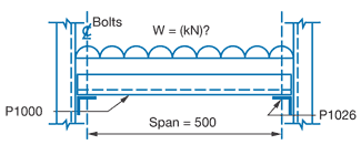
Example 1
What is the uniformly distributed load capacity of a P1000 section used as a beam to span 500mm if P1026 connectors are used to support the beam?
Step 1
- Find beam load at maximum permissible stress.
- From P1000 Beam and Column in this Tab Section, 500mm and Section P1000, W = 7.42kN.
Step 2
- Find load capacity of connectors.
- From Safe Bearing Loads in this Tab Section, for P1000 section supported on P1026 connectors;
Support load = 4.1kN
Beam load = 2 x support load = 2 x 4.1 = 8.2kN.
Step 3
- Check deflection limitations.
- No special deflection considerations apply.
Step 4
- Select smallest load value from Step 1 to 3.
- Smallest value is 7.42kN
- To convert to mass units divide by 0.0098, hence load capacity W = 7.42/0.0098 = 757kg uniformly distributed.
|
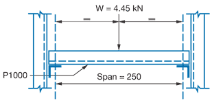
Example 2
A beam of 250mm span is to carry a central point load of 4.45kN. Check if P1000 section is a satisfactory beam and
if so, what type of connector should be used for supports
and what is the resultant central deflection.
Step 1
- Convert point load to equivalent uniformly distributed load by multiplying by 2 (see note on point loads).
- Equivalent U.D.L. = 4.45 x 2 = 8.9kN.
Step 2
- Compare with beam load capacity for P1000 section spanning 250mm. From P1000 Beam and Columns in this Tab Section.
Tabulated value = 14.83kN.
- Since this is greater than load to be applied, the P1000 section is satisfactory.
Step 3
- Determine support loads, which are each half the applied load.
Support load = 2.23kN.
Step 4
- Select appropriate connector from Safe Bearing Loads in this Tab Section.
- Recommended load for P1026 supporting P1000 = 9.5kN.
- As the P1026 connectors exceed the required support load of 2.23kN, use P1026 connectors at each end.
Step 5
- Calculate central Deflection of beam from

(See P1000 Elements of Section in this Tab Section)
- From Beam load table for P1000 section with

- From example data and step 1 above

- Substituting values in formula

As this is the value for the equivalent uniformly applied load a correction is necessary to account for a central point load. This is done by multiplying the uniform load deflection by 0.8 (see Notes to Tables).
Hence deflection under applied point load:
= 0.10 x 0.8 = 0.08mm.
|